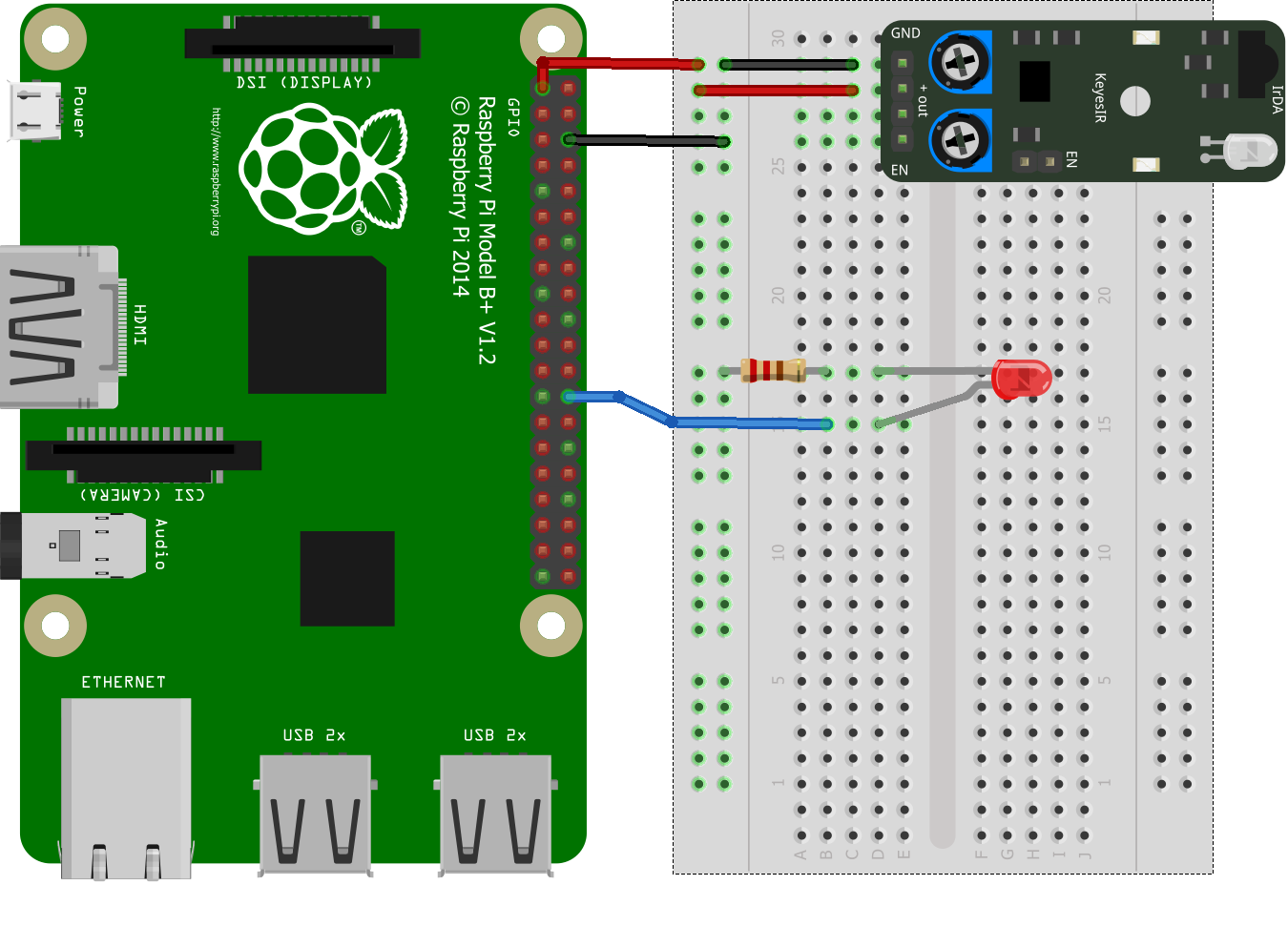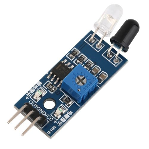
IR Sensor:

Specification:
Raspberry Pi:
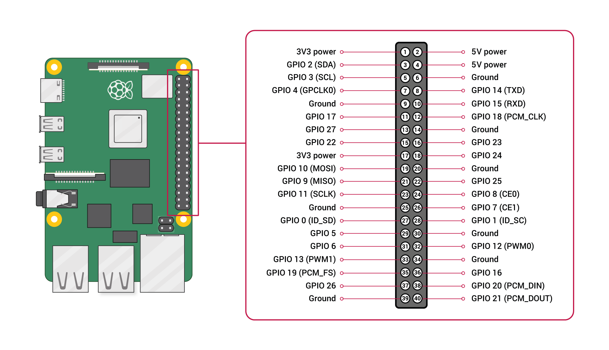
Pin configuration:
1. Vin: Two 5v pins and two 3v3 pins used for providing power supply, where processor works on 3.3v.